مقدمة
بالنسبة لمصنعي المعدات الأصلية (OEMs) للآلات الزراعية ومعدات البناء والشاحنات القلابة والمنصات المتنقلة المتخصصة، يعد اختيار بنية صمام التحكم الاتجاهي الهيدروليكي المناسب أحد أهم القرارات أثناء تطوير الماكينة. يعمل مشعب الصمام كجهاز عصبي مركزي للآلة، حيث يحدد سرعة المحرك، والقدرة على حمل الحمل، والأداء الحراري، وموثوقية النظام بشكل عام.
يمكن أن يؤدي الاختيار غير الصحيح لاختيار الصمام - مثل تحديد مشعب صمام صغير الحجم أو تحديد حالة مركز التخزين المؤقت غير المتوافقة - إلى قصور شديد في النظام، وارتفاع درجة حرارة السوائل بشكل مفرط، وانجراف غير منتظم للمشغل، وفشل مبكر للمكونات. وعلى العكس من ذلك، فإن الإفراط في تحديد حجم الصمام يزيد من أبعاد الغلاف ووزن السيارة وتكاليف الإنتاج دون فائدة تشغيلية.
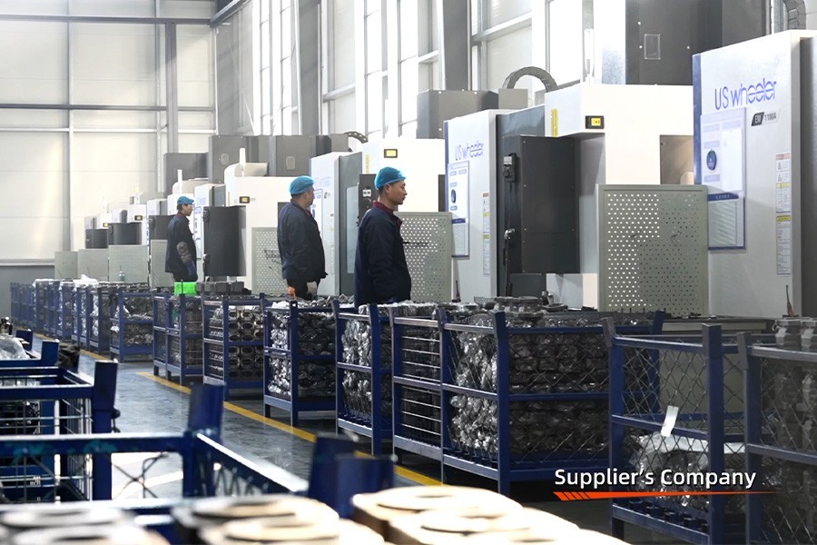
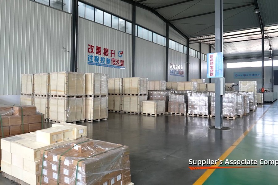
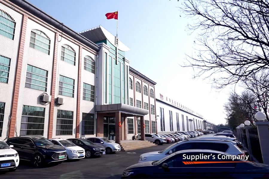
في شركة Boxinhuasheng Hydraulic Technology Co., Ltd.، تعاون فريقنا الهندسي مع مصنعي المعدات الأصلية للمعدات لأكثر من 25 عامًا. بدعم من 35 من كبار المهندسين الهيدروليكيين، و4 مرافق تصنيع، وأكثر من 260 ماكينة CNC، وشهادة الجودة الكاملة IATF 16949، نقوم بتصنيع صمامات مخصصة أحادية الكتلة وصمامات مقطعية يتم تصديرها إلى أكثر من 80 دولة.
يوضح هذا الدليل سبعة مبادئ هندسية أساسية لاختيار صمامات التحكم الاتجاهي الهيدروليكية لتطبيقات معدات OEM.
المبدأ 1: مقارنة بنية الصمام الأحادي الكتلة مع الصمام المقطعي
القرار الهيكلي الأول الذي يواجه مهندس نظام OEM هو الاختيار بين أصمام أحادي الكتلةأو أصمام مقطعي (معياري)..
+-------------------------------------------------------------------------+
|                  قطعة واحدة مقابل. مقارنة الصمامات المقطعية |
+----------+--------------------------------------+------+
| معلمة التحديد | صمام أحادي الكتلة | صمام مقطعي |
+----------+--------------------------------------+------+
| بناء المساكن | كتلة حديد الزهر المفردة| العمل المعياري |
|                          | (من 1 إلى 7 مكبات) | أقسام (Tie-Rodded)|
| تسرب النزاهة | استثنائي (لا يوجد وسط | يتطلب أختام دائرية |
|                          | الأختام المشتركة القسم) | بين الأقسام |
| المغلف المادي | مدمجة وخفيفة الوزن | الجسم المعياري الموسع|
| مرونة الدائرة | تخطيط التخزين المؤقت الثابت | عالي (إضافة/إزالة |
|                          |                       | أقسام العمل) |
| تطبيق OEM الأساسي | جرارات، لوادر، | أوناش، حفارات، |
|                          | شاحنات قلابة | معدات الغابات |
| تكلفة المكون الأولي | فعالة من حيث التكلفة | وحدات بريميوم |
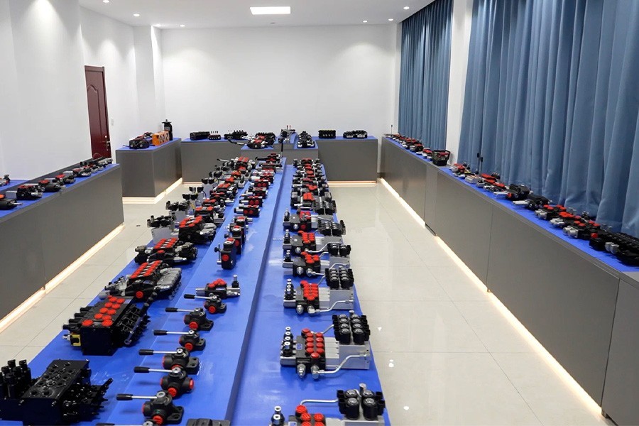
+----------+--------------------------------------+------+- صمامات أحادية الكتلة: مصبوب كجسم واحد من حديد الدكتايل عالي الشد (QT500-7). يزيل البناء أحادي الكتلة موانع التسرب بين الأقسام، مما يوفر منعًا فائقًا للتسرب في ظل الاهتزازات العالية والضغط العالي (حتى 31.5 ميجا باسكال). مثالية لآلات الإنتاج القياسية ذات الحجم الكبير حيث تكون تعديلات الدوائر نادرة.
- الصمامات المقطعية: يتم تجميعها من أقسام المدخل والعمل والمخرج الفردية المثبتة بقضبان ربط شديدة التحمل. توفر الصمامات المقطعية مرونة فائقة، مما يسمح لمصنعي المعدات الأصلية بدمج صمامات التنفيس المساعدة، والصمامات المضادة للتجويف، والأقسام الكهربائية المتناسبة في مجموعة واحدة مخصصة.
المبدأ 2: نوع الدائرة الهيدروليكية (مركز مفتوح مقابل مركز مغلق / مستشعر للحمل)
إن مطابقة تخطيط المعرض الداخلي للصمام مع بنية المضخة الهيدروليكية أمر غير قابل للتفاوض:
- أنظمة مضخات الإزاحة الثابتة (مركز مفتوح): يستخدم مكبات مركزية ترادفية. عندما تكون البكرات محايدة، يمر تدفق المضخة بحرية عبر الممر الجانبي إلى الخزان بأقل ضغط، مما يوفر الوقود.
- أنظمة الإزاحة المتغيرة / استشعار الحمل (مركز مغلق / LS): يستخدم مكبات مغلقة المركز. تعمل المنافذ المحايدة على منع تدفق المضخة، وتشير شبكة إشارات الحمل (LS) إلى التحكم في إزاحة المضخة لتقليل الخرج إلى الضغط الاحتياطي (حوالي 1.5-2.0 ميجا باسكال)، مما يزيد من كفاءة طاقة النظام.
المبدأ 3: تقييم التدفق وقيود السرعة
يتطلب تحديد حجم سعة التدفق الاسمية للصمام تحليل الحد الأقصى لطلب التدفق المتزامن بدلاً من متوسط إزاحة المضخة:
- سرعة ميناء العمل: يجب أن تظل سرعة السوائل داخل الأروقة الداخلية للصمام بينهما3.5 م/ث و6.0 م/ثتحت الحد الأقصى للتدفق.
- حدود انخفاض الضغط: عند التدفق المقدر، يجب ألا يتجاوز انخفاض الضغط الإجمالي ($\Delta P$) من منفذ P إلى منفذ العمل0.5 ميجا باسكال إلى 1.0 ميجا باسكال (5 إلى 10 بار)لتقليل تسخين الزيت.
- مخاطر الإفراط في الحجم: تزيد البكرات الكبيرة بشكل مفرط من متطلبات قوة النقل وتقلل من التحكم الدقيق في القياس في مواضع سفر البكرة المنخفضة.
المبدأ 4: ملف قياس التخزين المؤقت ومتطلبات التحكم في المشغل
تتطلب وظائف الماكينة المختلفة خصائص مميزة لقياس البكرة:
┌────────────────────────── ──────────────────────────┐
                  │ دليل اختيار قياس التخزين المؤقت OEM │
                  └─────────────────────────┬ ──────────────────────────┘
                                              │
         ┌──────────────────── ────────────┴───────── ─────────────┬─────── ─────────────────────┐
         ▼ ▼ ▼ ▼
┌────────────────┐ ┌────────────────┐ ┌────────────────┐ ┌────────────────┐
│ القياس الخطي │ │ التقدمي V- │ │ بكرة المحرك │ │ بكرة تعويم │
│ (ذراع الرافعة القياسي) │ │ الشق (الرافعة الدقيقة) │ │ (A & B إلى الخزان) │ │ (مزرعة ذات 4 مواضع) │
└────────────────┘ └────────────────┘ └────────────────┘ └────────────────┘- بكرات مركز المحرك: في الوضع المحايد، يتصل منفذا العمل A وB مباشرة بمعرض الخزان (T) بينما يكون P مسدودًا. وهذا يسمح للمحركات الهيدروليكية بالتوقف دون حدوث صدمة هيدروليكية.
- تعويم بكرات الموقف: يتميز بموقع احتجاز رابع يربط صالات العرض A وB وT معًا. ضروري للمحاريث الزراعية ودلاء التحميل لتتبع خطوط الأرض بحرية.
المبدأ الخامس: تكامل طريقة التشغيل
تجمع منصات ماكينات تصنيع المعدات الأصلية الحديثة بشكل متزايد بين أذرع التحكم اليدوية وعصا التحكم الإلكترونية:
- رافعة يدوية مباشرة: الروابط الميكانيكية للمعدات القوية ومنخفضة التكلفة.
- طيار هوائي / هيدروليكي عن بعد: قوة رافعة منخفضة داخل كابينة المشغل.
- الكهروهيدروليكية النسبية (تشغيل/إيقاف أو 12 فولت/24 فولت PWM): يتكامل مباشرة مع وحدات التحكم الدقيقة في الماكينة، مما يتيح تحديد موضع ذراع الرافعة تلقائيًا، والتحكم في تكنولوجيا المعلومات، وتشغيل المعدات الزراعية الموجهة بنظام تحديد المواقع العالمي (GPS).
المبدأ السادس: معايير نقل الخيوط وواجهات الختم
تعمل شركات تصنيع المعدات الأصلية العالمية في أسواق متنوعة بمعايير متميزة لخيوط منفذ السوائل. تقوم شركة Boxinhuasheng بتصنيع أجسام الصمامات بأربعة ملفات تعريف ملولبة موحدة:
- SAE O-Ring Boss (ORB - خيوط UNF): المعيار الأساسي لمصنعي المعدات الأصلية في أمريكا الشمالية؛ يوفر أداءً فائقًا بدون تسرب تحت طفرات الضغط.
- BSPP (خيط G مع ختم متماسك): المعيار السائد عبر صانعي الآلات الأوروبيين.
- متري ISO 6149: معيار الخيط المتري العالمي مع تجويف الختم الدائري.
- NPT / NPTF (خيط الأنابيب المدبب): خيار الخيط التقليدي لصيانة المعدات القديمة.
المبدأ السابع: إدارة الجودة ودعم الهندسة المشتركة للموردين
لا يمكن الاعتماد على الصمام إلا بقدر ما يمكن الاعتماد عليه في عملية التصنيع الخاصة بالمورد. عند اختيار شريك صمام OEM، يجب أن يطلب صانعو المعدات ما يلي:
- اختبار محاكاة عبء العمل بنسبة 100%: تم التحقق من الاختبار عبر 100% من الصمامات النهائية على مناضد اختبار آلية (تقوم شركة Boxinhuasheng بتشغيل أكثر من 30 منضدة اختبار).
- شهادة جودة السيارات: شهادة IATF 16949 النشطة والتحقق من مصنع SGS من جهة خارجية.
- قدرات الهندسة المشتركة: الوصول المباشر إلى كبار المهندسين الهيدروليكيين لتصميم CAD ثلاثي الأبعاد، وتخصيص درجة التخزين المؤقت، وأخذ عينات النموذج الأولي خلال فترات زمنية قصيرة.
خاتمة
يتطلب اختيار صمام التحكم الاتجاهي الهيدروليكي الصحيح تحقيق التوازن بين البنية الهيكلية وديناميكيات السوائل وقياس التخزين المؤقت والتشغيل وشهادة الجودة. من خلال تقييم الخيارات أحادية الكتلة مقابل الخيارات المقطعية، وتحسين ملفات تعريف قياس التخزين المؤقت، والشراكة مع إحدى الشركات المصنعة القائمة، يعمل صانعو الآلات OEM على تحسين أداء المعدات ومتانتها على المدى الطويل.
تقدم شركة Boxinhuasheng Hydraulic Technology Co., Ltd. أكثر من 25 عامًا من الخبرة في تصنيع المعدات الأصلية، و35 من كبار المهندسين، وقدرة سنوية تبلغ 1.5 مليون وحدة، وضمان الجودة الكامل IATF 16949.
للتشاور مع فريقنا الهندسي أو طلب نماذج CAD ثلاثية الأبعاد لمشاريع صمامات OEM، قم بزيارة الموقعwww.chinesehydraulic.com.