مقدمة
في الأنظمة الهيدروليكية المتنقلة والصناعية ذات الضغط العالي، تخضع الكفاءة التشغيلية ودقة التشغيل ومتانة المكونات على المدى الطويل للتفاعلات الديناميكية المعقدة والسوائل. عندما يُظهر صمام التحكم الاتجاهي الهيدروليكي ربطًا بكرة، أو تسربًا داخليًا، أو استجابة بطيئة - أو عندما تتعرض مضخة تروس لتدهور حجمي - نادرًا ما يكون السبب الجذري هو خطأ ميكانيكي معزول. وفي أغلب الأحيان، ينشأ ذلك من عوامل تشغيلية تؤثر على تفاوتات المكونات وخصائص السوائل.
في المعدات المتنقلة التي تعمل عند ضغوط تصل إلى 31.5 ميجا باسكال (315 بار) وتتقلب درجات حرارة الزيت من -20 درجة مئوية إلى +80 درجة مئوية، يتطلب الحفاظ على أداء مستقر للمكونات رقابة صارمة على متغيرات التشغيل.
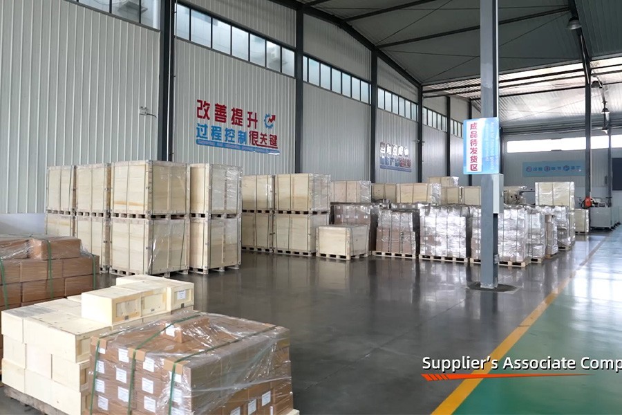
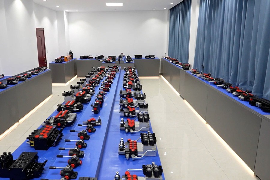
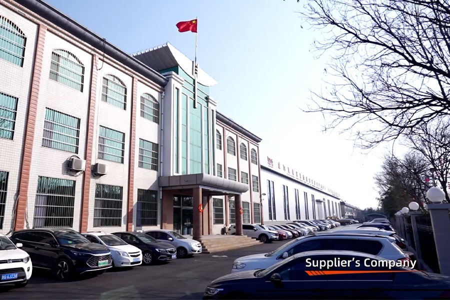
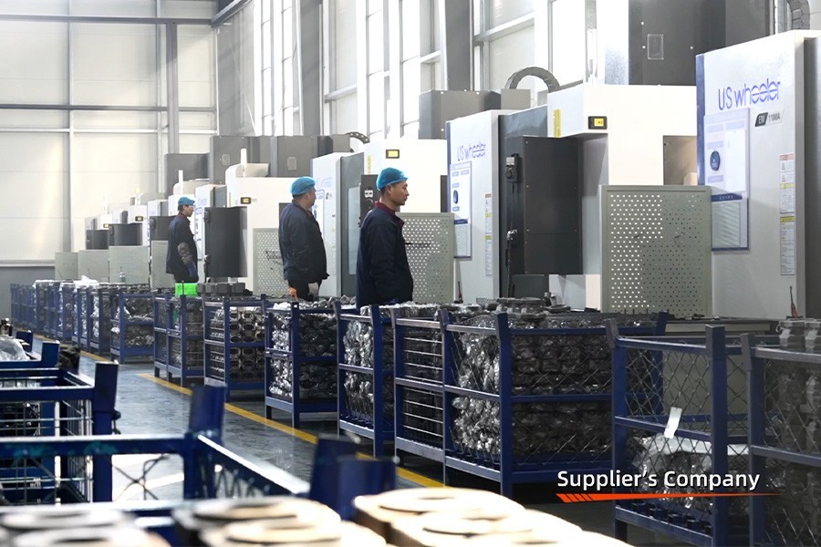
في شركة Boxinhuasheng Hydraulic Technology Co., Ltd.، يقوم فريقنا الهندسي بتحليل بيانات دورة حياة المكونات عبر أكثر من 25 عامًا من الخبرة في التصنيع. نقوم بتشغيل حرم جامعي مساحته 68000 متر مربع مدعومًا بـ 35 من كبار المهندسين الهيدروليكيين، وأكثر من 260 ماكينة CNC، وأكثر من 30 مقعد اختبار معتمد وفقًا لمعايير IATF 16949، ونقوم بتصميم صمامات التحكم الاتجاهي الهيدروليكية، ومضخات التروس، ووحدات مأخذ الطاقة (PTO) لتحمل الضغوط التشغيلية الشديدة.
توضح هذه المقالة بالتفصيل خمسة عوامل هندسية مهمة تحدد أداء المكونات الهيدروليكية وتوفر إرشادات عملية لزيادة موثوقية النظام إلى الحد الأقصى.
العامل 1: تلوث السوائل ومراقبة النظافة ISO 4406
من المعروف عالميًا أن التلوث بالجسيمات هو السبب الأكبر لتدهور المكونات الهيدروليكية، وهو ما يمثل ما يصل إلى 80% من حالات فشل النظام المبكرة.
+-------------------------------------------------------------------------+
|                  أنواع تلوث السوائل وتأثيرها |
+------------------------+------------------------------------------------+
| فئة الملوث | آلية الضرر |
+------------------------+------------------------------------------------+
| الجسيمات الدقيقة الصلبة | الحز الكاشطة لأراضي البكرة، وحفر الشحذ، |
| (سيليكا، رقائق معدنية) | وألواح جانبية للعتاد. يسرع التسرب الداخلي|
| جزيئات بحجم الطمي | سد فجوات إزالة البكرة؛ يؤدي إلى التخزين المؤقت|
| (< 5 ميكرون) | ملزمة وملف لولبي |
| مياه حرة ومذابة | يسرع أكسدة السوائل والتجويف و|
|                        | تشكيل الصدأ على مكبات الصلب الأرضية |
| فقاعات الهواء المحبوسة | يسبب تآكل التجويف في تروس المضخة، والضوضاء،|
|                        | واستجابة المحرك الإسفنجي |
+------------------------+------------------------------------------------+
لحماية الخلوصات الدقيقة من البكرة إلى التجويف في حدود 0.002 مم (2 ميكرون)، يجب أن يحافظ زيت النظام على مستويات نظافة صارمة وفقًا لـمعايير الأيزو 4406. بالنسبة للصمامات التناسبية ذات الضغط العالي ومضخات التروس، يجب الحفاظ على نظافة السوائل عندكود الأيزو 4406 16/14/11أو نظافة.
العامل 2: التباين الحراري وقص لزوجة الزيت الهيدروليكي
يؤدي الزيت الهيدروليكي أدوارًا مزدوجة: نقل طاقة السوائل وتشحيم الأسطح المنزلقة الداخلية. تتغير لزوجة الزيت ($\nu$) ديناميكيًا مع درجة حرارة التشغيل:
$$\nu(T) = A \cdot e^{\frac{B}{T}}$$
درجة حرارة الزيت منخفضة (-20 درجة مئوية) ──► اللزوجة العالية ──► مفرطة ΔP، تجويف، تبديل بكرة بطيء
درجة الحرارة المثالية (+50 درجة مئوية) ──► اللزوجة المثالية ──► كفاءة حجمية عالية وتزييت
ارتفاع درجة حرارة الزيت (+80 درجة مئوية) ──► لزوجة منخفضة ──► تسرب داخلي مرتفع، وتآكل، وتلف الختم- اللزوجة عالية جدًا (بدء التشغيل البارد): يزيد من مقاومة قص السوائل، ويزيد من انخفاض الضغط ($\Delta P$) عبر الأروقة الداخلية، ويقيد شفط المضخة، مما يسبب تجويف المضخة.
- اللزوجة منخفضة جدًا (ارتفاع درجة الحرارة> 80 درجة مئوية): يقلل من سمك طبقة التشحيم الحدودية، مما يسرع الاتصال المعدني بين الأجزاء المتحركة. تنخفض الكفاءة الحجمية عندما يتجاوز السائل الأراضي التخزينية في صالات الخزان.
العامل 3: تفاوتات الأبعاد وخلوصات التخزين المؤقت إلى التجويف
يعتمد التصميم الميكانيكي للصمامات الاتجاهية ذات البكرة المنزلقة على الخلوصات الدقيقة التي يتم التحكم فيها بين القطر الخارجي لبكرة الصمام والقطر الداخلي لتجويف الغلاف.
+-------------------------------------------------------------------------+
|                  BOXINHUASHENG قياسات تخليص البكرة |
+-------------------------------------------------------+
| نطاق الخلوص الشعاعي | النتيجة الوظيفية |
+-------------------------------------------------------+
| الخلوصات < 0.004 مم | خطر الارتباط الحراري المفرط. للغاية |
|                              | حساسة للتلوث بالطمي |
| الخلوصات 0.006 - 0.012 ملم | التوازن الأمثل: تسرب داخلي منخفض |
|                              | مع إزاحة سلسة للبكرة |
| الخلوص > 0.018 ملم | ارتفاع التسرب الداخلي. فقدان الاسطوانة |
|                              | القدرة على تحمل الحمولة |
+-------------------------------------------------------+
تستخدم Boxinhuasheng آلات شحذ الماس متعددة المحاور للحفاظ على أسطوانة التجويف بالداخل0.002 ملم (2 ميكرون)مع خشونة سطحية $R_a< 0.2\ \mu m$, ensuring stable clearance performance across operating temperature ranges.
العامل 4: ارتفاع الضغط وإدارة الصدمات الهيدروليكية
في الآلات المتنقلة الثقيلة، يؤدي الإغلاق المفاجئ للصمام، أو عكس الاتجاه السريع، أو تأثيرات الدلو إلى توليد موجات صدمات هيدروليكية شديدة (تأثير المطرقة المائية). يمكن أن تصل طفرات الضغط الذروة1.5 إلى 2.0 مرة ضغط العمل الاسمي:
$$P_{spike} = P_{working} + \rho \cdot c \cdot \Delta v$$
حيث $\rho$ هي كثافة السوائل، $c$ هي سرعة الصوت في الزيت (~ 1300 م/ث)، و$\Delta v$ هو التغير في سرعة السوائل.
تشمل عواقب ارتفاع الضغط غير المخفف ما يلي:
- تكسير السكن في مصبوبات صمام الحديد الرمادي منخفضة الجودة.
- واجهات الختم الدائرية المنفوخة.
- تشوه نوابض صمام التنفيس الداخلي، مما يتسبب في انحراف الضغط.
يعالج Boxinhuasheng هذه المشكلة عن طريق صب مجمعات الصمامات منهاحديد الدكتايل عالي الشد (QT500-7)، يوفر الحد الأدنى من قوة الشد التي تصل إلى 500 ميجا باسكال ومقاومة التعب الاستثنائية تحت ضغط يصل إلى 31.5 ميجا باسكال.
العامل 5: مضاعفة الختم وتوافق السوائل
تحافظ الأختام الهيدروليكية (الحلقات الدائرية، والحلقات الاحتياطية، وأختام العمود) على سلامة السوائل الداخلية والخارجية. يعتمد أداء الختم على توافق المواد مع السوائل الهيدروليكية ودرجات حرارة التشغيل:
- مطاط النتريل (NBR): اختيار الختم القياسي للزيوت الهيدروليكية المعدنية؛ نطاق التشغيل -30 درجة مئوية إلى +100 درجة مئوية.
- مطاط الفلوروكربون (FKM / Viton): مخصص لتطبيقات درجات الحرارة العالية (+200 درجة مئوية) أو السوائل الاصطناعية القابلة للتحلل الحيوي.
- البولي يوريثين (PU): يستخدم لأختام القضبان الديناميكية عالية الضغط بسبب البثق الاستثنائي ومقاومة التمزق.
قائمة مراجعة المشتري: ضمان العمر الافتراضي الأمثل للمكونات الهيدروليكية
يجب على مصنعي المعدات الأصلية ومديري الصيانة للمعدات تنفيذ أفضل الممارسات التشغيلية لتحسين أداء المكونات الهيدروليكية:
- [ ]فرض الترشيح الجزئي: قم بتركيب مرشحات خط الإرجاع المطلق 10 ميكرون وأنظمة الترشيح خارج الخط 3 ميكرون للحفاظ على رمز ISO 4406 16/14/11.
- [ ]مراقبة درجة حرارة الزيت: تركيب صمامات تحويلية ثرموستاتية على مبردات الزيت للحفاظ على درجات حرارة زيت التشغيل بين 45 درجة مئوية و60 درجة مئوية.
- [ ]تحديد العلب المصنوعة من حديد الدكتايل: تأكد من أن صمامات التحكم الاتجاهية المخصصة للآلات الثقيلة تستخدم مصبوبات حديد الدكتايل QT500-7 عالية الجودة.
- [ ]التحقق من اختبار المصنع: مكونات المصدر من الموردين الذين يفوضوناختبار محاكاة عبء العمل في نهاية الخط بنسبة 100%(قامت شركة Boxinhuasheng باختبار 100% من الوحدات الجاهزة).
خاتمة
يتطلب تحقيق أعلى أداء للمكونات الهيدروليكية إدارة نظافة السوائل، واللزوجة الحرارية، وتصاريح التصنيع، ومقاومة صدمات الضغط، وتوافق الختم. ومن خلال فهم هذه المتغيرات الهندسية، يقوم صانعو المعدات بتصميم آلات متنقلة ذات فترات خدمة أطول وتكاليف تشغيل أقل.
تطبق شركة Boxinhuasheng Hydraulic Technology Co., Ltd. أكثر من 25 عامًا من الخبرة في التصنيع، و35 من كبار المهندسين، وإجراءات الجودة IATF 16949، واختبار محاكاة عبء العمل بنسبة 100% عبر أكثر من 30 مقعدًا لإنتاج مكونات هيدروليكية متينة.
للتشاور مع القسم الهندسي لدينا أو طلب أوراق بيانات المكونات الفنية، قم بزيارةwww.chinesehydraulic.com.